
Select % Regrind Directly and Avoid “Double” Coloring
Clean Out Chute
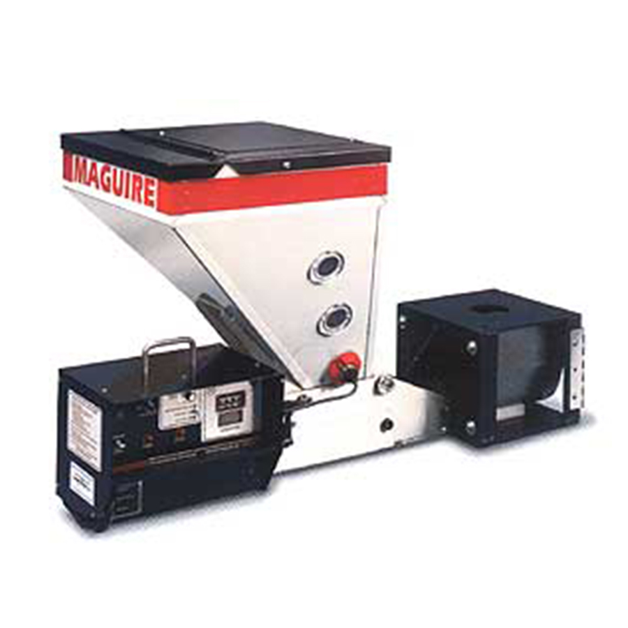
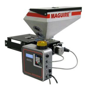
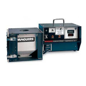
How Maguire Feeders Work
The controller signal cord is plugged into an outlet that is energized only when the process machine screw runs. During each screw return cycle (or continuous for extrusion), the motor runs and color is metered into the throat of the process machine.
The digital counter located on the face of the controller provides the means for predetermining the exact degree of auger rotation and, therefore, the precise amount of color that will be added. For injection molders, the motor will shut off when the preset count is reached during each cycle. For extruders, an optional digital tachometer feedback is available to ensure that motor speed is precisely regulated regardless of changing torque requirements or variations in plant voltage.
To determine the proper setting for the counter, a simple formula is used based on percentage of color required, a predetermined metering rate, and total shot weight in grams (or pounds per hour for extrusion applications).
The controller contains a 1/27 HP DC Permanent Magnet motor with variable speed control. In the standard configuration, the motor is close coupled to a heavy duty gearbox. As the motor turns, a “hall effect” pickup device on the motor sends 3 pulses per revolution to the microprocessor controlling it. The gearbox ratio of 53:1 means that 159 pulses (3×53) are received for every single revolution of the motor output shaft.
The thumbwheel switch on the controller should be set to the exact number of pulses that the motor is going to run before stopping. The microprocessor in the controller automatically multiplies the setting by a factor of 10. A setting of 16 on the controller will allow the controller to receive 160 pulses or run approximately 1 revolution before stopping (regardless of motor speed).
| Model | Auger Size | Max RPMs | Continuous Output lb/hr | Dispense | |
| Min | Max | (One Cycle) | |||
| MRF-8-34 | 1″ (25mm) | 55 | .05 (0.02 kg) | 58 (26.4 kg) | .05 cc |
| MRF-8-50 | 1″ (25mm) | 100 | .1 (0.05 kg) | 105 ( 47.7kg) | .08 cc |
| MRF-16-50 | 2″ (50mm) | 100 | .7 (0.32 kg) | 533 (242.3 kg) | .4 cc |
| MRF-16-94 | 2″ (50mm) | 188 | 1.6 (0.73 kg) | 1000 (445.5 kg) | .8 cc |
| MRF-16-160 | 2″ (50mm) | 320 | 8.0 (3.6 kg) | 1700 (772.7 kg) | 1.3 cc |

There are no reviews yet.